Remedial Wall ties for cavity wall tie replacement – which wall tie is best?
Ever since the mid 80’s when wall tie corrosion first became widespread, people have asked; which wall tie is best?
However, there really is no definitive answer for this. It’s like asking which car is best; is that a 4X4, sports coupé or saloon? They all do different things and it really depends on what is required.
So the answer to the question which wall tie is best is; the wall tie best suited for the job.
There are important reasons why different wall ties fulfil different roles and also how they work (or don’t work) in some situations. Driving a 4X4 is great for rough terrain, but you won’t win a road race in one.
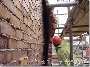
Wall tie corrosion leading to the collapse of this outer skin leaving the inner skin in place – Leeds
The parts common to all Cavity Wall Ties
Cavity wall ties share common parts (even the ones which look like they only have one part).
These are:
-
The inner fixing
-
The outer fixing
-
The section spanning the cavity
There are actually only a few basic types:
-
Mechanical fixing.
-
Resin/grout fixing.
-
Friction fix.
These can also be mixed, so for example you may have a tie with a mechanical external leaf fixing and a resin bonded or friction fixed inner leaf fixing.
This can become complicated for no reason if too much time is spent analysing the subtle and gross differences in the way these ties work. However, it is essential that surveyors understand the basic fundamentals of fixing technology so they can confidently specify the right cavity wall tie for the job.
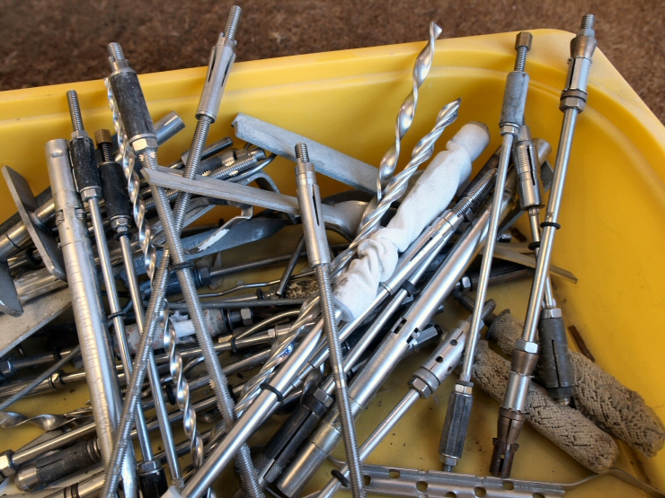
There are hundreds of models of remedial wall tie and all have three crucial parts…
So it is right to focus on the performance required, before looking at the available cavity wall ties. Let’s look at the three parts of the cavity wall tie:
The Inner leaf fixing.
Wall tie specialists sometime refer to this as the ‘remote’ fixing because it is unseen and remote from the operator on the scaffold. First though, we need to consider the base material we want to fix to; it could be made of timber, concrete, clinker block, common bricks, stone or engineering brick. If it’s masonry it will have very many mortar beds in it, both horizontal and vertical (the verticals are often referred to as ‘perps’ because they are perpendicular to the horizontal beds). If it is concrete it may be very hard or not so. It could be that the masonry units are hollow, with either large or small voids.
Mechanical wall ties
There’s little point in trying to get a reliable fix using a strong mechanical expansion wall tie in soft material. These include wide bed-joints, half empty perps or a soft clinker block. Mechanical expansion sleeves work by being expanded in the remote leaf pilot hole and this exerts expansive force around the hole. In weak substrates the base material can be easily damaged. This can reduce the performance of the inner leaf fixing hugely. This can happen immediately on installation of the wall tie, or several hours after installation; mechanical ties take time to ‘relax’ after installation so cannot be immediately tension tested. Of course expansion sleeve based wall ties cannot be used in timber frame, these would split the timber and again, the fixing would be ruined.
It’s a similar story with hollow blocks and perforations. The mechanical wall tie fix is achieved by the interaction between the forces expanding the sleeve and the substrate resisting it – a void is like trying to achieve a fix in fresh air; hopeless. In some respects the same thing happens in empty perp joints; the tie may waste a lot of the expansion action, growing to fill the gap between the bricks. In this situation a fix may be achieved but often, only temporarily. Move an expansion sleeve tie a bit to the right or left of a half empty perp and it may be no better – the lack of support for the side of the brick may just result in the brick failing, during tie expansion, with a vertical crack, alowing the brick to expand with the wall tie – again the fix is poor.
These types of fixing are very good though, in strong hard substrates such as engineering bricks and dense concrete blockwork. This is provided the bed joints are avoided. They are fast and cheap on labour – simple to install and easy to tension test. In hard base materials they can offer truly epic performance and I’ve seen tension tests of up to 8kN in concrete using these ties. Of course 8kN is never needed so in some respects this is academic, but it does show what is possible.
What about a friction fix type cavity wall tie?
These are generally based on stainless steel helical extruded wire. They rely on the angled fins cutting a friction groove in the base material – sort of screwing in and providing a grip this way. Once installed they cannot turn to be screwed out again (without picking the house up and manipulating it like a Rubik’s cube), so the wall ties are held fast this way and they offer good performance. However, as with other mechanical type fixings they can be an issue in some situations. Very hard material will resist this ‘friction groove cutting’ so the wall tie, no matter how well driven into the pilot hole, may be in effect be ‘re-profiled’ by the hard base material, rather than profiling the substrate. There are ways around this, like increasing the diameter of the pilot hole a tiny fraction, using a 316 grade stainless steel (which is harder), or if the bed-joints are not too soft, install into that. They also don’t cope well with hollow blocks or perforated bricks (just like sleeve type cavity wall ties). If the friction grooved hole hits a void within say 30mm of the outer face of the inner leaf, the fix will be severely compromised. In very soft substrates adjustments can be made by using a larger diameter tie (reducing bearing stresses), or as with all wall ties, merely increasing the installation density.
As such these need careful consideration before specifying them – the condition of the inner leaf must be known first. These types of fixings excel in timber. I have experience of seeing these helical ties (Helifix Retro Ties), installed into timber frames within only a few millimetres of the edge, without splitting the wood. Provided good embedment is achieved, a useful and reliable tension can be obtained.
Resin or cement grouted cavity wall ties.
Taking the above into consideration it can be seen that both soft, hard and hollow substrates can be the undoing of some types of cavity wall ties. This applies to resin fixed ties and grouted anchors too. However there are subtle but important differences. When installing this type of tie any thoughts of the ties being ‘glued’ into the inner leaf should be forgotten. The adhesive fix is the least important aspect of these ties and in fact, most common resin bonded ties don’t offer an adhesive fix at all. Don’t be surprised by this – it’s a mistake many make. It seems plausible that when a cavity wall tie is pushed into a hole full of goo, that you are ‘gluing’ it into the wall. You are not.
In fact the common resin bonded fix is a mechanical action. This is due to the way these resins work; once mixed they are in a thixotropic but still quite viscous state. The chemical set begins quite soon (in warm weather), and the resin begins to harden. Good quality resin does not shrink when it sets, so soon the wall tie will be encapsulated in a very hard material, several time harder than concrete. Pulling the wall tie from the resin is nigh on impossible, without breaking the steel or if pulled hard enough, causing shear failure to the resin – this would take a massive force. Of course this means that the failure would occur at the weakest point? Yes, and that is the interface between the resin and the base material – the brick, concrete – timber or stone. Resin is harder than all of these materials and it will not fail first. This is why the fix is a ‘mechanical one’ the difference is that the resin exerts no mechanical force on the substrate to achieve a fix – we do not need the balance between the expansion and resistance that sleeved mechanical ties need. We do not need to consider if the remote leaf is too hard to be effectively ‘friction grooved’. We merely need a good clean interface between the resin and the substrate. This is the rub.
Resin applied into a dirty and dusty hole will be mechanically fixed to the dust and so the dust, being free flowing, will merely act as a release agent for the resin. If tension is applied the resin/dust interface will fail and you’ll be looking at a wall tie lollipop with a crunchy crumb coating.
Care is needed to clean the remote hole of this lubricating dust before the resin is injected. That done, the resin is placed and as the tie is installed the displacement helps to ‘cement’ that interface. Any hole – yes even a diamond cored one, is rough enough to have ridges and grooves in it, which the resin will form to. Thus when the resin is hard, the fixing will resist any force applied ‘mechanically’ just as if you’d placed a manhole cover key into the recessed hole to lift a heavy manhole cover. If a heavy duty tension rig is used you will destroy the tie or the brick it is in, before the resin fails. Once set the inner leaf fixing can be tested immediately as there is no need to wait for any expansion forces to be absorbed or for the material to relax – job done.
Cold weather can extend resin cure times – hot weather can work the other way and cause resin to set in the application guns and feed tubes.
Of course there are always some issues; hollow blocks and perforations have to be adjusted for. With resin ties, small gauze sleeves can be inserted to support ther resin whilst the wall tie is inserted and to stop the resin leaking away. Cementitious systems are available with integrated expansion socks. These expand as the grout is injected and are very effective – though not cheap. However, whilst tying hollow structures is tough on any system, it’s usually much cheaper than a re-build would be. Cintec International’s grouted anchor system is the best known and is remarkably flexible in use. Helifix’s SockFix system is also excellent though less adaptable. Both these systems are only available to highly specialised and qualified contractors like eh… me (Brick Tie LTD, sorry, couldn’t resist).
Hardened resin will soften at temperatures as low as 500C so it should not be used if extended fire resistance is essential. In these cases cementitious or mechanical fix ties are preferred. Cementitious materials can be used without a sock if the substrate is sound and free of large voids. The hole still needs to be cleaned, but with water, rather than air or brush.
The outer leaf fixing.
Well you’d think that this was exactly the same as the inner but there are things unique to it. The good news is that it is usually visible. This means you can install the tie in a pilot hole drilled in the optimum place – be that in the face of the brick or stone or in the bed joint. This is not a given, as of course sometimes the ties need to be installed through render or pebbledash. In fact it used to bother me years ago that some manufacturers would state that their ties needed to be installed ‘centre of brick – to centre of brick’ how on earth can you do this if you can’t see them due to render and of course due to the inner being covered by the outer?
Anyway, all of the fixing problems discussed in the first part of this post apply – plus some more.
When a hole is drilled into a brick, it is not really drilled, in the way say, that a wood bit drills wood, or an auger drills into soil. The masonry is actually pulverised by the hammer action of the bit. Try drilling a half-decent brick with hammer off and see how long it takes. What this means is that a lot of extra impact force is distributed through the material as the drill bit works its way in. Depending on how strong the material is, the diameter of the drill bit and the power of the hammer – the masonry will fail at some point. This causes the back of the brick or stone to be broken away before the hole reached the inner face. This leaves a crater like hole in the inner face – much bigger than the hole drilled in the outer part of the brick (think teenager squeezing a small spot that explodes onto the bathroom mirror).
In some cases the ‘spall’ may be quite deep, perhaps taking 25mm or more from the brick section, In effect the outer leaf is now thinner than it was. Most remedial wall ties will accommodate this loss of section. However, sometimes the spall may be more severe; particularly in soft bricks or when large rotary hammer drills are used. A 110mm brick may lose a third of its thickness when the back is ‘blown’ off. So the brick looks great on the outside but is now only 64mm deep. This is the worst case but the loss of 30mm or so is quite common. This raises issues about contamination of the cavity, especially when it is full of cavity wall insulation. Moreover, it also presents cavity wall tie fixing difficulties:
Mechanical sleeved wall ties often have a sleeve perhaps 50mm long. This is usually recessed 12 to 25mm from the face of the brick. It’s common to look up a cavity via boroscope and see up to half of the sleeve exposed in the cavity because the back of the brick is missing (in other words in a void – read about voids and mechanical wall ties above).
There are ways around this – smaller drilling machines, smaller diameter pilot holes too. Mechanical expansion ties should not be placed in the bed joints so that is not an option.
Helical or Friction fix cavity wall ties – external leaf
Friction fix ties also suffer from reduced embedment in the outer leaf if the drilling causes excess spalling. However, helical ties usually require only a small pilot hole, so this is possibility is reduced. However, this raises another outer leaf conundrum; if a friction fix helical tie is driven through a small pilot hole how is the inner leaf fixing checked? Any experienced wall tie installation technician will tell you that he can often tell if he is going to get a good fix, by the feedback he gets from the inner leaf; if the drilling action gives him consistent and firm feedback, then there is a good reason to feel confidant. In addition, with a resin bonded fix he will ‘feel’ the resistance the resin gives as it is displaced when he installs the stainless steel tie, be that a Helical type or a tie based on a deformed bar. Nevertheless in accordance with good practice, a random tension test (or pull-out as it is known), will be needed to confirm things.
This tension test cannot be randomly done if a friction type fix is driven through the outer leaf and on into the inner. The tie is lost and held fast in the outer leaf and there is no chance of a supervisor fixing an adapter there to test it. It can be carefully over-cored (this destroys the outer fix), and the the inner pull tested, but this is a waste of time as it is not random and the distress imposed on the tie as it is exposed, can dislodge the inner, giving false negatives. In addition, the driving action through the outer leaf offers some resistance, so the operator can feel that, but he cannot effectively feel the tie reacting in the inner leaf (as it is in firm contact with the outer). If he is inserting the tie into a void or, if the outer leaf is so hard it has deformed the tie so that it cannot cut an effective friction groove in the inner leaf – he will not know. Meanwhile the tie will be in the wall, but doing next to nothing.
Resin grouted wall ties – outer leaf
Resin and grouted fixings also struggle with the above problems in the outer leaf. One area is the lack of a ‘blind’ hole to help the resin displacement. Remember that the resin in the inner leaf has nowhere to go when the stainless steel wall tie is inserted into it. This means it is relativity easy to get a good encapsulation of the tie and good firm interface between the resin and the internal circumference of the pilot hole. This problem is helped by the design of some ties, particularly the helical type. Many of these come with a plastic ring which is used to in effect block the rear of the outer leaf hole, giving the resin something to come up against. In practice though, the small diameter of these ties and small cross section also helps, because with care, the wall tie installer can place the resin tube over the tie and inject it along the full length, withdrawing the injection tube as he/she does so. A clean pilot hole is essential, in fact it is more important in the outer leaf because of the reduced pressure of displacement, compared to the inner leaf displacement.
The issue of spalling of the rear face of the outer leaf masonry applies here also. It will frustrate the benefit of the plastic ring I mention, as a spalled rear is in effect an huge increase in hole circumference, so the resin will not be retained by the ring. If this happens then it is important that the tie is long enough to be fully encapsulated in the outer section of the brick, perhaps to within 5/10mm of the face. It is one reason why as a specialist, when using resin/grouted tie, I tend to specify a tie about 25mm longer that the required minimum; the extra length may be come in handy. Nevertheless it is far better to reduce spalling in the first place where possible; sharp new bits, right size machine and if using resin, consider the bed-joint instead of the masonry units.
Of course with cementitious grouts, water is used to clean the hole so this is less of an issue. Cementitious grouts can be damaged by frost or dried too quickly in very sunny hot weather and precautions should be in place to mitigate this. These include wetting of the outer leaf (though not to the extent the grout is washed out), and covering the wall with damp hessian. The larger diameter grouted sock anchors are much less prone to this because they are simply bigger At least 25mm diameter and often much more A 25mm recess is required for these anchors, which can be covered or mortared up, with a sacrificial plug if required – simple rake the frost or dried-up plug out and re-point it later.
The section of wall tie crossing the cavity
The role of this is to provide a connection between parts one and two. Of course it must be strong enough in tension and compression, and also allow slight differential movement horizontally and vertically, especially in more modern buildings and timber frame structures. Ties should ideally be installed with a slight slope of 50 upward to the inner leaf to avoid rainwater running across to the inner masonry. In practice most ties are designed to stop this using a drip feature, such a deformation in the tie itself or a retro-fitted drip ring, which should in the centre of the cavity.
Where neoprene or plastic drip rings are supplied some care is needed. When removed from the box they are usually centred on the tie exactly between the expansion sleeves (if the ties are mechanical), and in the middle with resin bonded ties. Taking into account that the tie is usually installed slightly off centre, with perhaps 60/70mm in the inner and more than that in the outer, this is sometimes the wrong location. The ring should be moved a little further towards the inner leaf if required (this will vary from job to job). If this is not done the ring may end up in, or against the outer skin and could be bypassed or bridged. Helical ties avoid this because the design results in a repeated drip feature; far less likely to be defeated in practice.
Defeat of the drip feature is a real problem in cavities filled with cavity wall insulation (CWI). It’s a problem both in cavities where wall ties have been installed after the CWI and in those where it is installed later. The drip feature works by disturbing the water on the part of the tie in the outer leaf, so a drop is formed at he drip and the water is shed naturally. |Once the wall tie is encased in insulation this action may be disturbed, such that water may be wicked along the insulation/wall tie interface or the drip action disturbed in the insulation itself, so a wet patch of insulation is created directly below the wall tie. |In cases where a large diameter hole is drilled in the inner leaf (>10mm), the drill spoil from that action will line the hole through the insulation with the drill spoil. This is impossible to remove effectively, especially with bonded beads or blown fibre. If the drip feature is defeated in this situation the dripping water is located at a patch of dirty insulation, mixed with drilling dust. It will then absorb the water and compress the insulation via a slight slumping action. Whilst actual penetrating damp is rare due to this, as houses become more humid and air-tight, there may be a rise in localised mould issues, related to the wall tie induced cold bridges. It must be carefully considered on westerly facing and exposed sites.
In cases where the insulation is injected after the wall ties the same issue applies, though the problem of the inner leaf drill spoil is avoided.
One area where the presence of insulation is crucial is in cavity wall tie installation on recently built homes. Sometimes these have insulation in-situ, which is in panel form, held in place by the wall tie insulation clips. Drilling pilot holes through these is a high risk activity for several reasons:
-
The drill bit can ‘grab’ the fibrous type pannels and pull them into firm contact with the outer skin of masonry.
-
Spalled material from the inner face of the outer leaf can become ‘wedged’ across the small gap between the insulation and the outer leaf – perhaps causing bridging
-
Drill spoil is pulled into the insulation and also, to a lesser extent down the small gap between the inner leaf and the insulation,
In cases of remedial wall tie work being required on relativity new houses, the above points need to be considered and controls used to mitigate the issues. I tend to favour using Helical ties for friction fixing in the inner leaf, which will need a very small diameter pilot hole for the remote fixing. A small hole reduces the quantity of drill spoil and small high speed drill bits are less ‘grabby’ than larger diameter drill bits used for resin bonded or mechanical sleeve ties. These also have the handy repeating drip feature, so they are less likely to form a bridge from the outer leaf to the insulation.
Resin fixing is favoured for the outer leaf in these circumstances; usually the client would prefer to avoid visible holes in the nice new stone or brick, so a bed-joint location can be used. The slightly larger external leaf pilot hole allows random testing of the inner leaf fixings – essential when on a site where there has already been quality control problems. This rules out the use of ‘one shot’ Helical friction-fix anchors, which cannot be randomly tested.
Some factors effecting Tensile and compressive strength of wall ties.
The stability of the inner leaf structure is ‘borrowed’ by the outer leaf via the wall ties. Wind loading will act on the slender outer leaf and only the wall ties stop it being peeled away (or pushed closed).
Whilst tests are available on site for tensile performance, some assumptions are made regarding compression. This is simply because on-site testing for compression is just not practical. However some rules apply:
-
Wider cavities reduce tensile strength very slightly initially with higher reduction as the width increases.
-
These same increases in width can reduce compressive strength considerably, well before tensile strength is noticeably reduced.
The above can be factored in by using stronger ties in very wide cavities or by increasing the installation density. Very thin section ‘wire’ style remedial ties should not be used in cavities over abut 1o0mm without a structural engineers advice. It is very likely that an alternative tie or a higher installation density will be needed.
Remember that the effects on compressive strength are more pronounced with wider cavities. This is due to bending and the slenderness ratio of the tie material. A good tension test in these cases does not signify good compressive performance.
So the above outlines the three parts and roles of the wall tie. All cavity wall ties must meet the needs and even those with one physical piece, are three part anchors really.
All ties depend upon the base material and as all engineers will confirm, any member is only as strong as its weakest point.
Dry Rot.
I aim to add some nice images to illustrate the above points – probably whilst I recover from my hernia operation….
I have a question which Helical tie is better HeliFix DryFix or Thor Wall tie. I have seen both and the Thor tie appears to be stronger.
Hi Sue,
That is a good question as they are virtually the same. I should point out that in my day job I am a Helifix Approved Installer so I have a bias. That said, in years past I was a Thor Helical approved installer so I am very familiar with both.
If you read my post you will see that there really is a strong indicator that the tie itself is not really the most important element is a successful remedial installation. In practice a Helifx Dryfix or equivelent Thor Helical item will work well or fail. Success is dependent on matching the type of tie to the substrate material and then installing it correctly.
There are very subtle differences in the way the Helifx and Tor Helical ties are made. Talk to each manufacturer and they will give you a convincing reason why their tie is ‘the best’. In truth there is little between them and the difference are too subtle to impact on the practical outcome of an installation. The Thor item is designed to be a little more accurate in the profiling of the helical section – very neat and a point in its favour. However, the Helifix is pre-tensioned during its formation so any tiny flaws in the wire are found in advance – a point in the Helifix ties favour.
You pay your money and take your choice Sue. The post makes it clear that there is much more to remedial wall tie work than the brand of wall tie.
Bryan
An informative and well written assessment of the options. Thank you. I’m in South Wales and will not be able to use your services. However it puts me in a better position when talking to local contractors. Cheers. Mk